
Why Basements and Underground Parking Lose Mobile Signal — and How to Fix It
Why basements and underground car parks lose mobile coverage, and how to plan a donor antenna, ceiling antenna count, host power and isolation that actually works.
On this page
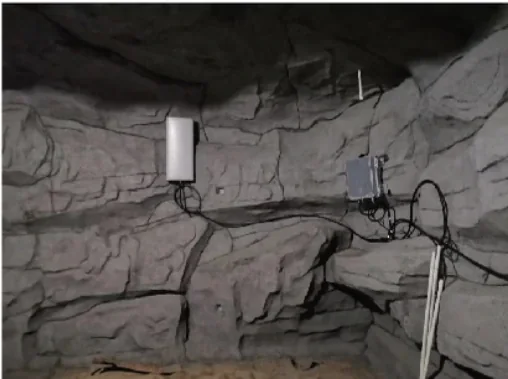
Basements and underground car parks are predictable dead zones. Concrete slabs, retaining walls and the earth around them absorb or reflect most of the outdoor signal, and the only openings are usually a ramp, a stairwell and a lift shaft. A phone may work at the top of the ramp and lose the network two bays in. Unlike an office, there is no window wall to rely on, so the answer has to be an indoor distribution system fed by a donor antenna placed where outdoor coverage actually exists.
This guide covers donor position, antenna density, host sizing, isolation, emergency calls and maintenance. The ranges below are planning figures.
Why does mobile signal disappear below ground?
Three factors stack up. The first is material loss. A 200 mm reinforced concrete wall or slab typically costs 15–25 dB, and a basement usually has several of them between the outside world and the parking bay. Soil is worse: a metre of earth over a structure can add tens of dB, which is why a basement roof garden is not a radio window.
| Obstruction between the outdoor source and the basement | Typical loss | Planning note |
|---|---|---|
| Single glazing | 2–4 dB | Almost transparent; relevant only at a shallow lightwell |
| Reinforced concrete wall | 15–25 dB | Main loss in most basements; thickness and rebar density matter |
| Concrete floor slab | 15–25 dB | Each level adds another slab; B2 is much worse than B1 |
| Soil overburden | 20–40 dB or more | Effectively opaque; treat as no path |
| Metal shutter or service door | 20–30 dB | Common at ramps and loading entrances |
| Low-E coated glass | 20–30 dB | Can make a lightwell useless for signal |
The second factor is aperture. Signal enters through the ramp mouth, stairwells, ventilation shafts and lift shafts. Coverage is strongest near them and falls away quickly. The third is depth: every level down adds another slab and a longer path to the entrance. A grade-level reading of -70 dBm can become -95 dBm in B1 and -110 dBm in B2, which is already below the useful range for many phones.
Can a booster work when there is no signal at the basement entrance?
No. A booster amplifies an existing signal; it does not create one. The donor antenna must be installed where a usable outdoor signal exists, normally on the roof or at grade beside the building. If the level at every candidate position is below the system threshold, a repeater will amplify noise and raise the noise floor for the surrounding cell.
Measure at grade on all sides of the building, not only at the main entrance. Record RSRP, band and cell ID for each operator. Better than -85 dBm is comfortable; -85 to -95 dBm is workable but makes donor gain, height and feeder loss critical; -95 to -110 dBm is a donor-link project; below -110 dBm, discuss another backhaul. A window-mounted donor is only an option when the window itself has a usable signal, which is uncommon below grade. The measurement guide shows how to collect these readings.
How many ceiling antennas does a parking level need?
Start with the area type, then adjust for ceiling height, columns and ramps. A normal parking ceiling of 2.4–3.2 m allows antennas at 2.4–2.8 m; a 4–6 m ceiling needs about 20–30% more antennas, or directional antennas aimed along the drive lanes.
| Area | Starting density | Note |
|---|---|---|
| Open parking bays | 1 antenna per 400–500 m² | Adjust for columns, low beams and parked vans |
| Storage and archive rooms | 1 antenna per 200–300 m² | Walls and shelving absorb more than open parking |
| Corridors | 1 antenna per 30–50 m | Directional antennas can follow the corridor |
| Ramps | 1 antenna per 20–30 m of slope | Cover the whole ramp, including the transition to grade |
| Plant, electrical and pump rooms | 1 antenna per room | Metal equipment and walls create local shadows |
| Lift lobbies | 1 antenna per lobby | Check the lift phone and the lobby separately |
Car count is a useful cross-check. One space including its share of drive aisle is roughly 25–30 m², so 100 spaces is about 2,500–3,000 m² and 5–7 antennas; 300 spaces is about 7,500–9,000 m² and 15–20 antennas. Add antennas for ramps, plant rooms and lift lobbies rather than stretching the parking density to cover them.
How do you size the host for a basement or parking garage?
Size the antenna count first, then choose a host that can feed every branch with acceptable loss. The table below is a starting point for a single level; multi-level projects usually need fiber remote units or one host per level.
| Basement scale | Typical host output | Service antennas | Distribution note |
|---|---|---|---|
| Up to 3,000 m², one level | 33–37 dBm | 6–10 | One or two branches; short cable runs |
| 3,000–8,000 m², one level | 37–40 dBm | 10–20 | Multiple branches; check loss at each splitter |
| 8,000–15,000 m², one level | 40–43 dBm | 20–36 | 1/2” feeder; keep runs short and balanced |
| Multiple levels or above 15,000 m² | 43 dBm class plus remote units | 36+ | Fiber between levels; isolate each level separately |
A two-way splitter costs about 3.5 dB, a four-way about 7 dB and an eight-way about 10.5 dB. At 1,800 MHz, 1/2” feeder loses roughly 0.06–0.09 dB per metre, while 50-5 cable loses 0.2–0.3 dB per metre. Keep host-to-antenna loss below about 10 dB and reserve 20–25% spare ports. For a small basement, a 30 dBm host such as the AL-30 can cover roughly 100–3,000 m²; a 37 dBm HAG-19-27T is a better fit for 3,000–5,000 m² with several antenna branches. Use a low-loss coaxial cable sized to the run, not the thinnest cable that fits the conduit.
Where should the donor antenna go, and how much isolation does it need?
Mount the donor at the highest practical point with a clear path to the serving sector: roof, parapet or a mast at grade. Test three or four positions before drilling; a move of one or two metres can change the reading by 6–10 dB, and a parapet or lift overrun can put the antenna in a shadow.
Keep the donor and service antennas at least 8–10 m apart, preferably with a concrete slab, a wall or a roof structure between them. On a basement project the separation is often vertical: donor on the roof, service antennas in B1, with the roof slab providing 15–25 dB of extra isolation. Route the feeder down a shaft or riser that is not next to a service antenna, and seal the entry point.
Use a directional donor with enough gain for the measured level. An omni on a roof picks up unwanted sectors and makes isolation harder.
What causes self-oscillation, and what do ALC and AGC actually do?
Self-oscillation is a feedback loop. The service antenna radiates a boosted signal, the donor antenna picks part of it up, the host amplifies it again, and the loop repeats. The result is a rising noise floor, distorted output and interference across the operator’s sector. It can happen even when the antennas are 8 m apart if a metal wall or a stairwell reflects energy back to the donor.
ALC, automatic level control, reduces gain when the output approaches the rated limit. AGC, automatic gain control, adjusts to changes in the donor input. Isolation detection goes further and reduces or shuts down the output when the loop is detected. These features protect the host but do not replace a proper installation. Commission with 5–10 dB of gain margin below the isolation limit, use directional service antennas where possible, and if the unit alarms, improve separation or reduce gain instead of adding power.
Will the system cover emergency call points, lift lobbies and ramps?
Emergency call boxes, lift emergency phones and fire alarm panels are often the most important devices in a basement, and the most likely to be forgotten in a design. Put an antenna near each call point, test an actual call rather than only a signal reading, and provide backup power for the booster and any active equipment. If the building has a lift, decide early whether the car or the shaft needs its own antenna; lift coverage usually cannot be achieved from the parking ceiling alone.
Ramps need continuous coverage from the basement level up to grade, because that is where a call is most likely to drop during handover. Columns create shadows in open parking, so check the layout before fixing the antenna grid. Plant rooms with metal doors and dense equipment may need a dedicated antenna even when the surrounding parking has good signal.
What maintenance does an underground system need?
Inspect connectors and cable jackets annually, especially outdoor joints and the cable entry at the roof. Check the booster’s alarm log and confirm that it is running at the commissioned gain rather than having reduced itself after an isolation event. Test the emergency call points and lift phones at the same time.
Re-test coverage after any renovation, repaving or change of tenant, because new walls, metal shelving or equipment can create fresh shadows. If the site has a UPS or battery backup, replace the battery on its service interval and record the date. Keep the as-built plan, antenna positions and gain settings with the building documentation so the next technician does not have to start from zero.
What should you send to get a basement design?
Send the grade-level RSRP on each side of the building for each operator, a few readings inside the basement, the band and cell ID, a floor plan with levels and ramp positions, the car count, ceiling height, plant room locations and photos of the ramp, roof and any existing cable route. With those inputs a supplier can size the donor, the host and the antenna grid, and tell you whether the site is a standard coverage project or a donor-limited one.
The basement and parking solution page shows the typical architecture, and the building materials guide explains the loss figures in more detail. If the outdoor level is the limiting factor, read the three-cause diagnostic framework before ordering equipment.
Frequently asked questions
Can the donor antenna be mounted at a basement window?
Only if the signal at that window is genuinely usable, which is rare for a deep basement. A window-mounted donor is a compromise for shallow spaces; a roof or grade-level position with a clear path to the base station is normally much better. Measure both before deciding.
How many antennas does a 200-space underground car park need?
At roughly 25–30 m² per space including drive aisles, 200 spaces is about 5,000–6,000 m². At one antenna per 400–500 m² that is 10–15 antennas, before adding coverage for ramps, lift lobbies and plant rooms. Ceiling height and column spacing can push the count higher.
Will the system improve 4G and 5G equally?
It depends on the bands the host supports and the donor signal on each band. Higher frequencies generally suffer more loss through concrete and soil, so a 5G band may need more antennas or a higher-gain donor. Confirm the local bands before selecting a model.
Why does the booster alarm or shut down after installation?
The usual cause is insufficient isolation between the donor and service antennas. Reduce the gain, improve the physical separation or add a concrete wall or slab between them. Replacing the booster with a more powerful model makes the problem worse.
Do I need a separate system for each basement level?
Not always. One host can feed several levels if the splitter and cable loss budget allows it. For deep or large basements, fiber remote units or one host per level are more practical, because coaxial runs between levels add loss and make isolation harder.
How do I test coverage after installation?
Record RSRP at a grid of points on each level before and after, using the same phone or meter. Then make real calls at the worst points, test the emergency call box and lift phone if covered, and check that the booster shows no isolation alarm.
Related products
See All Products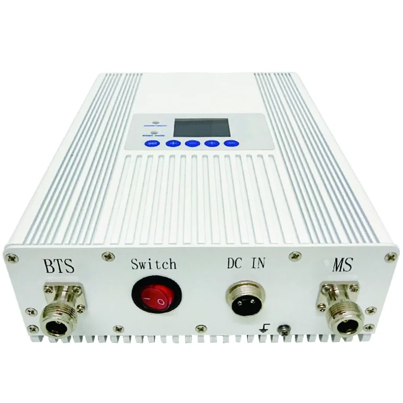
AL-30 Multi-Band LCD Signal Booster
Multi-band booster with LCD display, AGC and isolation detection for 100–3,000 m² coverage.
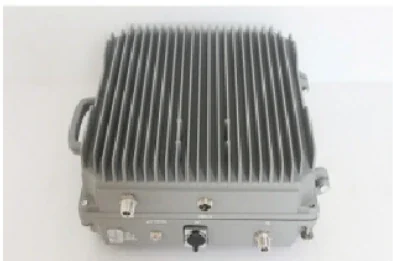
HAG-19-27T Single-Band Engineering Booster
37 dBm output with 75–85 dB gain for 3,000–5,000 m² coverage.
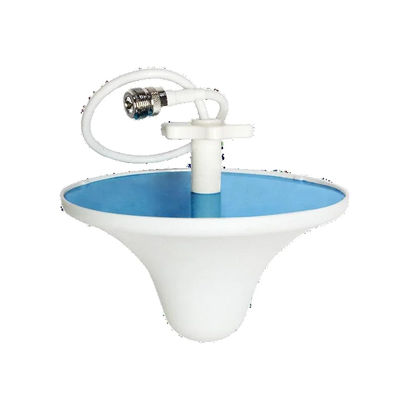
Indoor Omnidirectional Ceiling Antenna
3 dBi omnidirectional ceiling antenna for 800–2700 MHz.
View Details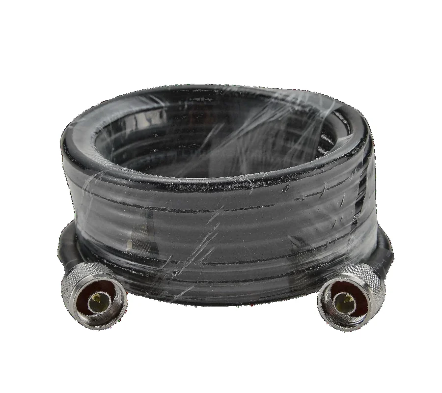
Low-Loss Coaxial Cable
Low-loss 50-5 and 1/2" coaxial cable with N male connectors.
View Details