
Vehicle Signal Booster Installation: What to Check Before You Start
A practical pre-installation checklist for car, truck, boat and RV signal boosters: antenna placement, isolation, power, cabling, compliance and testing.

On this page
A vehicle is a small metal room that moves. The body blocks the outdoor signal, the windows are the main aperture, and there is very little distance between the antenna that receives the network and the antenna that serves the phones inside. Add vibration, heat, moisture and a 12 V or 24 V electrical system, and a domestic booster kit starts to look like the wrong tool.
This guide covers what to confirm before drilling a single hole: the RF layout, antenna separation, power and fusing, cable routing, local compliance and the tests that prove the installation works. It applies to cars, vans, trucks, buses, motorhomes and boats.
Why is a vehicle cabin a difficult RF environment?
A car or boat cabin is a metal enclosure with glass openings. The roof, pillars and body attenuate the outdoor signal, while the windows let some energy in. The result is an uneven field: a phone may work on the dashboard and drop out in the rear seat. The cabin is small, so the outside donor antenna and the inside service antenna are close together.
That proximity creates the central installation problem. A booster amplifies both the downlink and the uplink. If the service antenna radiates back into the donor antenna, the booster sees its own output, raises gain and oscillates. The usual symptoms are an alarm, a shutdown, noise on the network or no improvement at all. Antenna separation and a realistic gain setting matter more than headline output power.
Vehicle hardware also has to survive motion. Choose a compact unit with secure mounting and protected connectors. The HAG-05-DP is a slim dual-band unit for tight spaces; the HAG-20T is a compact single-band model for small cabins. Neither substitutes for a proper antenna layout.
Where should the donor antenna be mounted?
Mount the donor antenna at the highest exterior point with a clear view toward the serving base station. On a car or van, that usually means the roof, not the dashboard, boot or inside a plastic bumper. On a boat, a mast or radar arch is normally better than the cabin roof. On a motorhome, keep the antenna clear of air-conditioning units, solar panels, satellite domes and roof racks.
The mount has to survive wind load and vibration. A magnetic mount is acceptable for a temporary test but is a poor long-term choice on a vehicle that is washed, driven at speed or exposed to salt water. Use a permanent mount with a sealed cable entry, and check that the antenna covers the bands you need. A wideband donor antenna covering 700–2700 MHz is more flexible than a single-band whip, but it must still be aimed correctly.
Keep the donor away from other radio antennas: VHF, AIS and GPS on a boat, and existing radio or camera cables on a vehicle. Do not mount it where it will radiate into the passenger cabin.
How do you keep the donor and service antennas isolated?
Isolation is the difference between the tower signal the donor antenna receives and the signal it accidentally receives from the service antenna. The booster can only operate when isolation is higher than its gain. A common planning rule is to keep at least 10–15 dB between the operating gain and the measured isolation.
In a vehicle, distance alone rarely provides that margin. A 75–85 dB booster in a 4–5 m cabin needs the vehicle body, a directional donor antenna and a reduced gain setting to stay stable. Put the service antenna low inside the cabin, away from the rear window and the donor cable. Do not put it under the windscreen when the donor is on the roof.
| Vehicle type | Donor antenna position | Service antenna position | Isolation approach |
|---|---|---|---|
| Sedan / SUV | Roof centre or rear roof | Under a seat or in the centre console | Roof and body between antennas; keep service low; reduce gain |
| Van / box truck | Roof above the cab | Cab ceiling or behind the dashboard | Metal bulkhead helps; keep donor above the cab; seal the entry |
| Bus / coach | Roof, away from AC units and destination signs | Ceiling above the passenger aisle | Long roof gives separation; use a directional donor; conduit the cable |
| RV / motorhome | Roof, clear of AC, solar and roof racks | Living-area ceiling, away from windows | Separate by several metres; avoid parallel cable runs; check 12 V supply |
| Boat / yacht | Mast or radar arch, high point | Cabin ceiling, away from the companionway | Vertical separation; keep clear of VHF/AIS; use marine-grade hardware |
If the booster still alarms at the required gain, the answer is not a larger amplifier. Reduce the gain, change the service antenna position, or move the donor antenna. A higher-power unit makes oscillation worse, not better.
How should the booster be powered and fused?
Use a stable DC supply within the booster’s rated input range. Check whether the vehicle is 12 V or 24 V, and confirm the unit’s input range; a 12 V unit needs a converter on a 24 V bus.
Protect the positive feed with a fuse close to the battery or distribution point; the fuse protects the cable, not only the booster. Use a circuit that is either ignition-switched or permanently live according to the owner’s preference, and label the circuit so the next technician can find it. Do not tap airbag, ABS, brake or engine-control circuits. Ground the unit to the chassis at a clean, corrosion-free point.
Disconnect the battery before working on the electrical system and follow the vehicle manufacturer’s procedure. For boats, use a dedicated breaker, tinned cable and a supply that can survive engine starting and low-voltage conditions. Leave access for service; a booster buried behind trim will overheat and cannot be diagnosed.
How should cables be routed, fixed and sealed?
Use a low-loss 50 Ω coaxial cable sized for the run. Keep the cable as short as practical, avoid sharp bends and keep it away from heat sources, moving parts and sharp metal edges. Secure it at regular intervals so vibration cannot fatigue the connector. Leave a small service loop at both ends, but do not coil excess cable tightly against the booster.
Every exterior penetration needs a grommet, sealant and a drip loop so water runs away from the entry point. Use UV-rated cable for outdoor runs and weatherproof the connector with self-amalgamating tape. On a boat, use tinned copper, sealed connectors and a route above the bilge. Label both ends of the cable; the next installer will thank you. The coaxial cable page lists the 50-5 and 1/2-inch options; choose the size by run length and loss budget, not by price alone.
Which compliance checks come before installation?
Rules for mobile boosters vary by country and sometimes by operator. Some markets require type approval, a licence, registration or written operator permission. Others restrict private repeaters, limit output power or prohibit them in vehicles altogether. A CE or FCC mark that is valid for one product in one market does not automatically authorise use in another.
Check the rules before you buy the hardware, especially for commercial fleets, taxis, buses and passenger vessels. Marine installations may fall under flag-state and coastal-state rules, and the vessel’s insurer may ask for a declaration. Keep the model number, approval number, serial number, installer details and test record with the vehicle or vessel. If the rules are unclear, ask the regulator or the operator in writing. The import checklist covers the documents worth collecting.
How do you test the installation before handover?
Test with the vehicle closed and the engine running, and compare the same measurement point with the booster off and on. Record RSRP or the received level in dBm, plus SINR where available. Do not rely on bars. Test every band and operator the vehicle actually uses, and test both voice and upload: a link that downloads quickly but cannot upload is not a working installation.
| Check | How to test | Pass criterion |
|---|---|---|
| Donor signal | Measure at the donor antenna or booster input | Stable and inside the booster’s rated input range |
| Isolation | Raise gain slowly and watch the status indicator | No oscillation or alarm at the required gain |
| Cabin coverage | Measure at front, middle and rear seats | Clear improvement over the booster-off baseline |
| Uplink | Make a call and run an upload test | Network accepts the connection; no repeated drops |
| Power | Measure voltage at the booster and check the fuse | Within the rated range; correct fuse fitted |
| Cabling | Pull-test, inspect bends and sealed entries | Secure, sealed and free of sharp bends |
| Thermal | Run for 30–60 minutes under load | No overheating, derating or shutdown |
| Compliance | Check the paperwork against the installed model | Approval or registration matches the unit |
Finish with a short drive or sea trial through a weak-signal area. If performance is unstable, review antenna separation and cable routing before changing equipment. Document the before-and-after readings; they are the only evidence that the installation did what it promised.
What are the most common installation mistakes?
The most common mistake is putting the donor antenna inside the vehicle, under the dashboard or in a plastic bumper. It may pick up some signal, but it also picks up the service antenna, and the booster will oscillate. The second is placing the service antenna next to the rear window, directly below the donor antenna. The third is running maximum gain in a small cabin.
Other frequent problems are an unfused positive lead, a cable crushed by trim or a door, an unsealed roof entry and a test that only checks bars at one seat. On boats, corrosion and water ingress cause more failures than RF design. On commercial fleets, a written checklist and a standard cable route matter as much as the hardware.
Start with the vehicle type, the donor position and the required bands. Then confirm the isolation plan, the power source and the local approval before drilling. The vehicles and marine solution page shows the intended layout, and the measurement guide explains how to record the baseline. A compact booster such as the HAG-10DB3P can be a better fit for a small cabin than a high-power unit.
Frequently asked questions
Can I install a home signal booster in a car?
Only if the model is designed for mobile installation. A full-size home booster is difficult to mount safely, may overheat in a closed cabin and usually has connectors that are not rated for vibration. Use a compact unit with a fused DC supply and a proper exterior antenna.
How far apart do the donor and service antennas need to be?
As far apart as the vehicle allows, with the body or roof between them. Separation alone is rarely enough at high gain, so the installation also needs a directional donor antenna and a reduced gain setting. A practical target is at least 10–15 dB of isolation above the operating gain.
Do I need to disconnect the vehicle battery during installation?
Yes, before working on the electrical system. Follow the vehicle manufacturer's procedure and do not tap airbag, ABS, brake or engine-control circuits. Use a fused positive feed taken from a suitable distribution point, and ground the booster to a clean chassis point.
Is a vehicle signal booster legal in my country?
Not everywhere. Some markets require type approval, a licence, registration or operator permission; others restrict or prohibit private boosters. A CE or FCC mark for one market does not automatically authorise use in another. Check the rules before purchase, especially for commercial fleets and passenger vessels.
Will a booster improve mobile data as well as voice?
It can, provided the booster covers the operator's bands and the outdoor signal is usable. Data needs a working uplink as well as a strong downlink, so test uploads and calls, not only download speed. In a congested cell, a booster cannot add network capacity.
Why does the booster alarm or shut down after installation?
The usual cause is insufficient isolation between the donor and service antennas, which makes the booster amplify its own output. Other causes are overdriving the input, a damaged cable or connector, or the wrong band configuration. Reduce gain and review the antenna layout before replacing the unit.
Related products
See All Products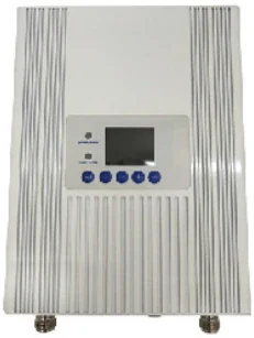
HAG-05-DP Compact Dual-Band Booster
Compact 20/27 dBm dual-band booster with ALC/AGC.
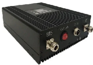
HAG-20T Compact Single-Band Booster
Small single-band booster covering 100–500 m² with low power consumption.
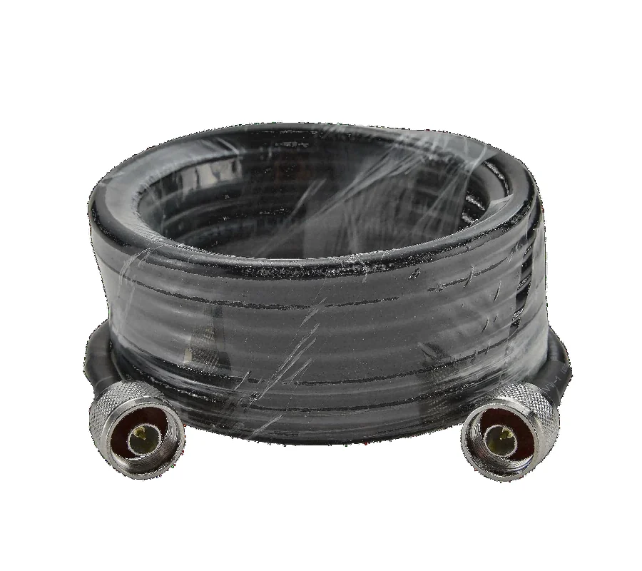
Low-Loss Coaxial Cable
Low-loss 50-5 and 1/2" coaxial cable with N male connectors.
View Details
HAG-10DB3P Compact Tri-Band Booster
Tri-band 10 dBm booster for homes, shops and small offices.