
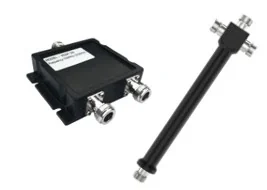
Product images are for reference. Final appearance is confirmed with the approved sample.
Cavity Power Splitter
Cavity power splitters divide the boosted signal between multiple indoor antennas. Two-way and three-way versions are available for 800–2700 MHz systems. The cavity construction provides low insertion loss and stable performance in distributed antenna installations.
- Frequency
- 800–2700 MHz
- Type
- 2-way / 3-way cavity splitter
- Connector
- N female
- Impedance
- 50 Ω
- Application
- Indoor antenna distribution
OEM/ODM customization is available. Frequency, housing, logo and packaging are confirmed per project.
Overview
Cavity power splitters divide the boosted signal between multiple indoor antennas. Two-way and three-way versions are available for 800–2700 MHz systems. The cavity construction provides low insertion loss and stable performance in distributed antenna installations.
- Low insertion loss
- Stable cavity construction
- Two-way and three-way options
- N female connectors
Technical Specifications
| Frequency | 800–2700 MHz |
|---|---|
| Type | 2-way / 3-way cavity splitter |
| Connector | N female |
| Impedance | 50 Ω |
| Application | Indoor antenna distribution |
Application Scenarios
Typical deployment scenarios for this model. Final configuration depends on on-site signal strength, building structure and coverage area.
- 01
Office antenna distribution
Distributes signal across a distributed antenna system, splitting coverage by zone and balancing level between branches.
- 02
Hotel and mall coverage
Covers guest rooms, shops, classrooms and public areas; indoor antennas are placed according to partitions and foot traffic.
- 03
Residential multi-floor systems
For indoor coverage in homes, apartments and villas; floor-by-floor antennas reduce weak-signal dead spots.
- 04
Commercial DAS projects
Distributes signal across a distributed antenna system, splitting coverage by zone and balancing level between branches.
Antenna count, cable routing and host power are confirmed after a site survey or project drawing review.
OEM / ODM Availability
Custom logo, frequency, housing and packaging options are available for this product. Minimum order quantities and tooling requirements are confirmed per project.
- Custom Logo
- Custom Frequency
- Custom Housing
- Packaging
Product datasheet
Detailed specifications, installation guidance and customization options are available on request. Tell us the model and project requirements and we will send the right document.
FAQ
Which frequency bands does CASP-2N / 3N support?
800–2700 MHz
What coverage area is CASP-2N / 3N suitable for?
Share the coverage area, floor plan, target bands, outdoor signal level and the number of service antennas you plan to use. Our engineering team will confirm the host power, antenna and cable configuration.
Can CASP-2N / 3N be customized for our brand?
Yes. Logo, frequency, housing and packaging customization are available. Minimum order quantities and tooling requirements are confirmed per project.
How do we confirm the final configuration for CASP-2N / 3N?
Share the coverage area, floor plan, target bands, outdoor signal level and the number of service antennas you plan to use. Our engineering team will confirm the host power, antenna and cable configuration.
Related Products
See All Products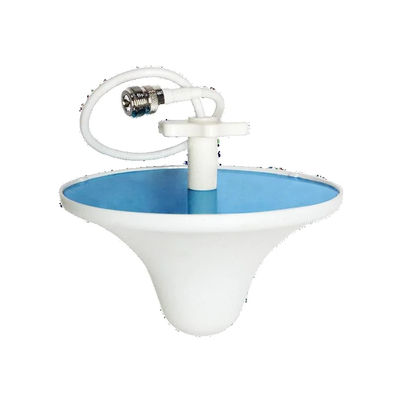
Indoor Omnidirectional Ceiling Antenna
3 dBi omnidirectional ceiling antenna for 800–2700 MHz.
View Details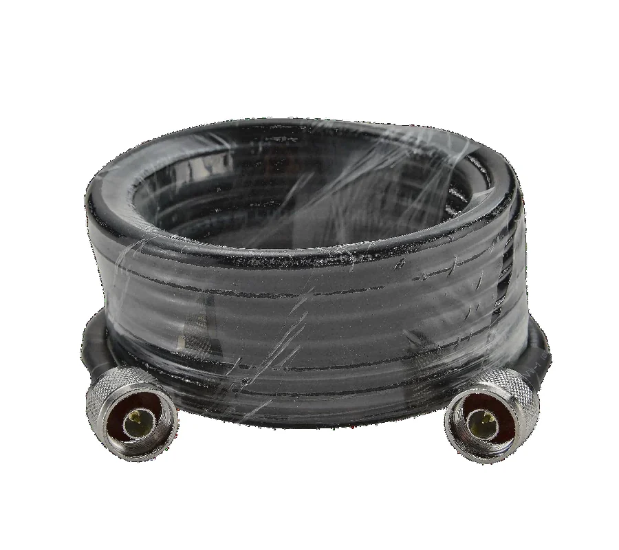
Low-Loss Coaxial Cable
Low-loss 50-5 and 1/2" coaxial cable with N male connectors.
View Details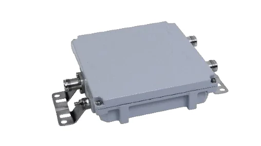
Cavity Combiner
2-in / 1-out cavity combiner for 800–2700 MHz systems.
View DetailsInterested in This Product?
Send us your project details and our team will recommend the right configuration.